![]()
|
|
|
Module#4 : Motors R ESEARCH AND RESULTSWe are interested in moving the rover at a reasonable speed so as to respond favourably to the signals sent by the microprocessor to the turning mechanism. There is also a time-lag between the signals sent by the sensor to the microcontroller and the microcontroller to respond, but this can be ruled out in comparison to the time required for the motors to respond. This is because the microcontroller works at a clock speed of approximately 2 MHz, and this suffices all our speed requirements in terms of data transfer. Three types of motors were mainly considered for steering the rover
While considering the advantages and disadvantages of the different motors we observed that the servo-motors have the following advantages:
The servo-motors also have the disadvantage that they do not have full rotation, they are usually designed to work within 60o span. In order to obtain complete rotation the servo-motor unit has to be disassembled and the plastic nib that restricts the rotation has to be cut off, and also the potentiometer has to be cutoff so as interface the microcontroller and then reassembled. These factors forced us abandon the use of servo motors. The DC motors have the following advantages:
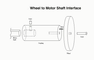
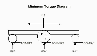
The DC motors have the disadvantage that the DC motors with gear boxes are not easily available, but once such a DC motor with the gear box is obtained DC motor is best suited for use in the rover design ,that too at a relatively lower cost as compared with the stepper motors. The shaft interface does not come with the DC motor , so we designed a coupling which we used to connect to the wheels. In our case , the vehicle travels only on flat surface so, the static friction is the maximum force acting on the wheels. The motor should be able to overcome the moment caused by static friction.
The minimum torque required by the motor must be greater than the sum of moments around the powered axial. With dual motor design each motor has to produce half the torque. The shaft interface does not come with the DC motor so we designed a coupling which we used to connect to the wheels. C OMPATIBILITY OF THE MOTORS:The Handy Board that we are using is designed for motors that will operate at 9 Volts and draw up to 1 ampere of current maximum. This includes LEGO motors and various motors sold by hobby houses. The Handy Board is not compatible with 3V to 5V motors available in toy cars. They are extremely noisy from an electrical point of view. They also draw a large amount of current thereby overloading the circuit. Also motors used in high-end radio cars are designed to draw up to 20 A of current and cannot be used with the 'rover'. P OWER REQUIREMENTS:The handy board's internal battery is rated for 9.6 V, which is generally adequate for running motors between 9 to 12 volts. However there are possibilities that some 6 V motors or some 12 V motors may not work properly. Certain bridge circuits can be used to bring the current requirement to the required level. The Handy Board's internal motor drivers are good for driving small D motors rated 6 V to 12 V, but they may not drive the high-end RC cars as mentioned earlier. The L293D replacement chips are only good for one ampere of current on a continuous basis. There are a few replacement circuits available that serve as a replacement :
C OULD ANY MOTOR BE USED?We have narrowed down our choices to the two following ones:
2. The Servo Motors:
|
|
1999 IEEE VESIT Student Branch Hits :
Webmaster : Saumitra Mohan Das |